DIP Switch Settings and Pin Definitions
Jumper and Internal Connector Placement
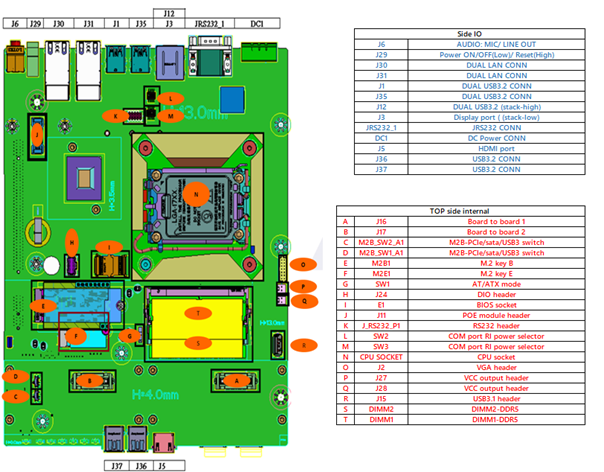
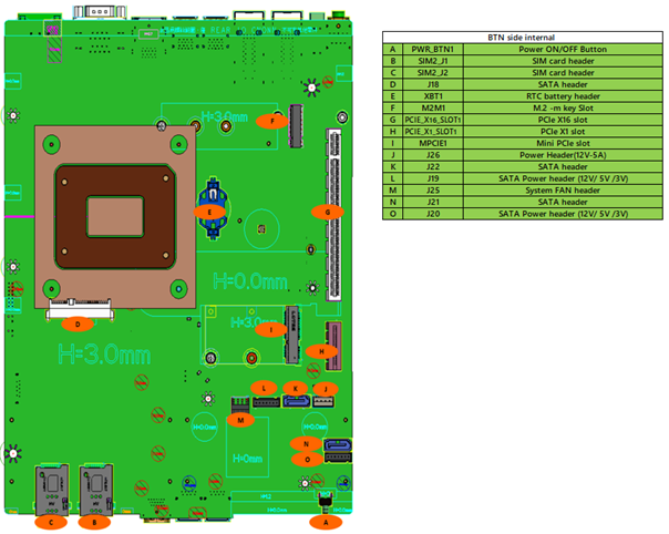
Overall Layout
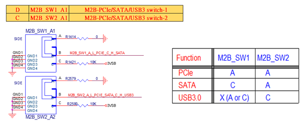
DIP Switch Settings
Internal Connector Pin Definition
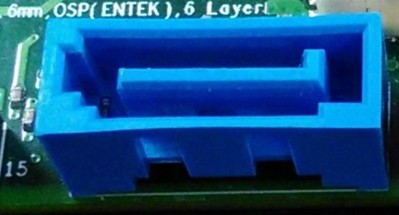
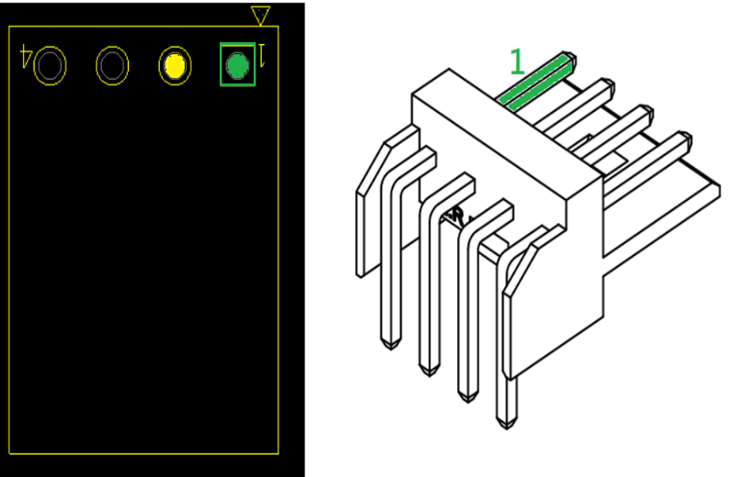
1st SATA Connector (Location J18)

Pin |
Signal Name |
|---|---|
P1-P3 |
VCC3 |
P4-P6 |
GND |
P7-P9 |
VCC |
P10 |
GND |
P11 |
RES |
P12 |
GND |
P13-P15 |
+12V |
S1 |
GND |
S2 |
SATAHDR_TXP0_C |
S3 |
SATAHDR_TXN0_C |
S4 |
GND |
S5 |
SATAHDR_RXN0_C |
S6 |
SATAHDR_RXP0_C |
S7 |
GND |
SATA Power Headers (Location J19/J20 - 2nd & 3rd SATA Power Headers)
Pin |
Signal Name |
|---|---|
1 |
VCC3 |
2 |
GND |
3-4 |
VCC |
5 |
GND |
6-7 |
+12V |
SATA Signal Headers (Location J19/J20 - 2nd & 3rd SATA Signal Headers)
Pin |
Signal Name |
Description |
|---|---|---|
1 |
GND |
Ground |
2 |
SATAHDR_TXP_C |
SATA Data Transmit (Positive) |
3 |
SATAHDR_TXN_C |
SATA Data Transmit (Negative) |
4 |
GND |
Ground |
5 |
SATAHDR_RXN_C |
SATA Data Receive (Negative) |
6 |
SATAHDR_RXP_C |
SATA Data Receive (Positive) |
7 |
GND |
Ground |
8 |
G1 |
GND |
9 |
G2 |
GND |
Fan Header (Location J25)
Pin |
Signal |
|---|---|
1 |
Ground |
2 |
+12V |
3 |
CPU_FAN_TACH |
4 |
CPU_FAN_CTRL |
12V/5A Power Headers for PoE Expansion (Location J26)
Pin |
Signal |
|---|---|
1 |
Ground |
2-3 |
+12V |
4 |
GND |
External Connector Pin Definitions
3-Pin Terminal Block for DC Input
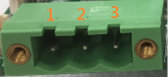
Pin |
Signal |
|---|---|
1 |
DC IN +9~48VIN |
2 |
N/A |
3 |
GND |
2-Pin Terminal Block for Remote Power ON/OFF and Reset
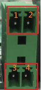
Pin |
Signal |
|---|---|
1 |
Ground |
2 |
EXT Reset |
3 |
Ground |
4 |
EXT_PWRBT_ON/OFF |
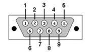
COM#1 / COM#2 / COM#3

Expansion Module DIO/COM
The DIO/COM module consists of two parts: Serial COM and Digital IO functions.
Please refer to the guideline for instructions on how to correctly set up this module.
COM Port Setting
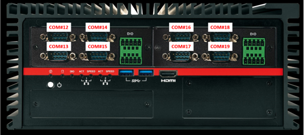
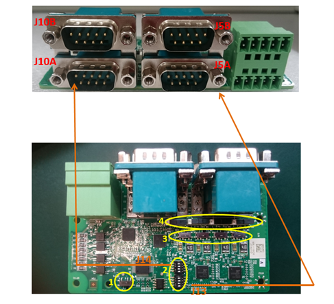
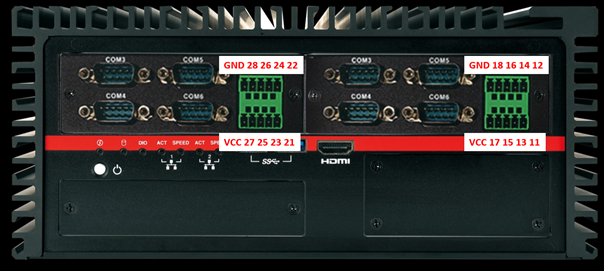
Location
The DIO/COM module has a total of 4 COM ports. These ports can be configured as:
RS232
RS422
RS485
Powered RS232
There are two types of Expansion COM drivers:
Standard non-fixed COM port order driver
Fixed COM order driver
If the fixed COM port order driver is installed, the positions will be as follows:
1st DIO/COM (Left Expansion Door)
2nd DIO/COM (Right Expansion Door)
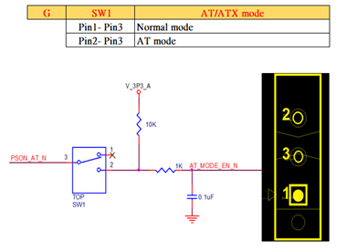
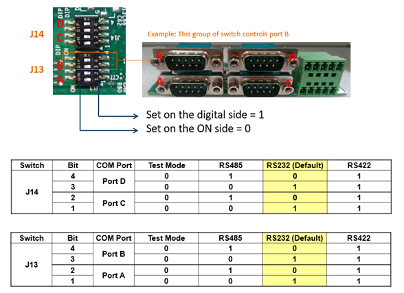
DIP Switch Function
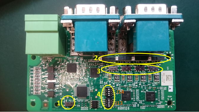
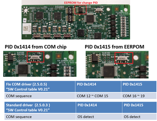
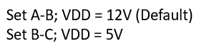
COM PID Selection Switch
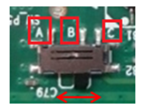
Set A-B: COM PID 0x1414 is determined by the UART controller (default).
Set B-C: COM PID 0x1415 is determined by EEPROM (for 2nd MS-48CDN-DT10).
PID and Driver Version Matrix Table
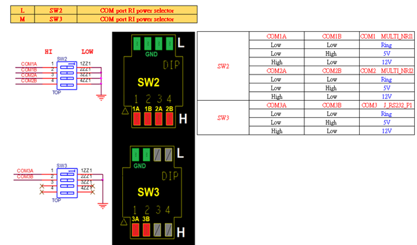
Powered COM Enable Switch
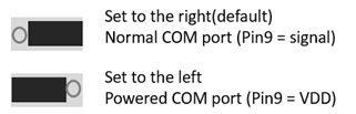
Powered COM Power Source Selection Switch
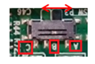
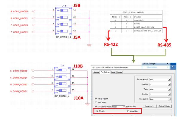
COM Mode Setting Switch
Driver Configuration Setting for RS485
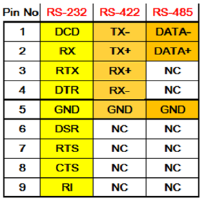
COM Port Pinout

Digital IO Port
The DIO/COM module has a total 8-bit GPIO, with the following positions:
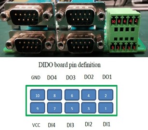
Left DIO Expansion / Right DIO Expansion
PIN |
HW |
Left DIO Order |
Right DIO Order |
Description |
|---|---|---|---|---|
1 |
DI_1 |
21 |
11 |
Digital Input 1 |
2 |
DO_1 |
22 |
12 |
Digital Output 1 |
3 |
DI_2 |
23 |
13 |
Digital Input 2 |
4 |
DO_2 |
24 |
14 |
Digital Output 2 |
5 |
DI_3 |
25 |
15 |
Digital Input 3 |
6 |
DO_3 |
26 |
16 |
Digital Output 3 |
7 |
DI_4 |
27 |
17 |
Digital Input 4 |
8 |
DO_4 |
28 |
18 |
Digital Output 4 |
9 |
VCC |
- |
- |
VCC |
10 |
GND |
- |
- |
Ground |
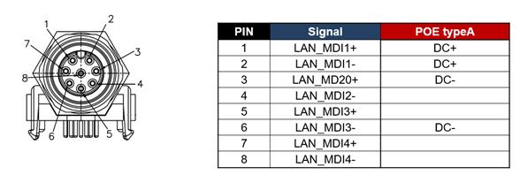
Expansion Module PoE-LAN M12
This module is a Giga LAN module supporting four M12-type interfaces.
Combined with a power module, it supports PoE (Type A).
M12 Code A LAN Module Pin Definitions